How To Solve Problem Based On Norton’s Theorem In Practical
In This Below Topic, We Will Discuss About “How To Solve Problem Based On Norton’s Theorem In Practical”.
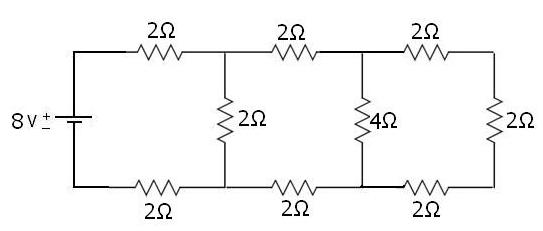
Below Is The Example Of A Circuit Which We Will Find Answer By Solving Through Norton’s Theorem Method.
Let’s Start.
Aim:- We Have To Find The Current In 4Ω Resistance In The Below Network Circuit By Using Norton’s Theorem.
Solution: - For Solving The Value Of Current Through 4Ω Resistance, We Will Follow The Same Step As Discussed In Our Previous Post.
(Click Here To Revise Your Practice)
FOR
FINDING RL: -
HERE, RL= 4Ω
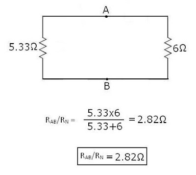
NEXT STEP TO FIND RN: -
For Finding RN, Just Find-out Equivalent B/w Removed Load-resistance.
As Below:-
NEXT STEP TO FIND IN/IS.C: -
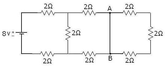
Next Step Is To Short-circuited Pt. A And Pt. B
Now Current In The Circuit Will Easily Pass Through The Short Circuited Path And Parallel Resistance Will Remove, As Shown Below:-
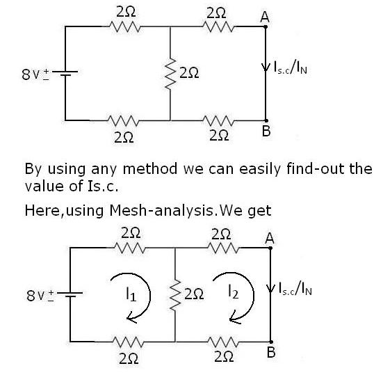
In Below We Have Two Loop Circuit For Which We Get Current Of Each By Using Kirchhoff’s Voltage Law(KVL).
APPLY
KVL IN LOOP 1ST:-
8-2I1-2I1-2I1+2I2 =0
-6I1+2I2 = -8 ··············· (1)
APPLY KVL IN LOOP 2ND:-
-2I2-2I2-2I2+2I1 =0
2I1-6I2 = 0 ··············· (2)
RESULT ON SOLVING, WE GET
I1 = 1.5A & I2 = 0.5A
HERE, I2= IS.C/ IN =
0.5A
RESULT
ON SOLVING, WE GET
I1 = 1.5A & I2 = 0.5A
HERE, I2= IS.C/ IN = 0.5A
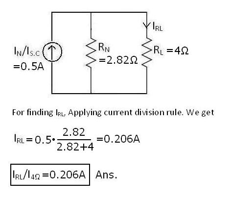
FINALLY, THE NORTON’S EQUIVALENT CIRCUIT IS,
Note:
Hope It Simplified Your Question And Answer Technique, Don’t Miss To Comments Your View. Thanks For Your Visit Our Website.
Trending Posts This Month:-
Solved Examples Problems On Star-Delta Transformation Or Conversion
Solved problem based on Norton’s Theorem
Solved Problem Based On Superposition Theorem
Example Solved Problems Based On Thevenin Theorem Circuit
Tricky Solutions For Equivalent Series-parallel Resistance Problems With Examples
Solved Problem Based On Maximum Power Transfer Theorem
Mesh-analysis - Loop-analysis -Maxwell's Current Analysis | Electrical
Delta To Star Transformation Or Delta To Star Conversion and Its Formulas
Superposition Theorem And Method Of Solving Superposition Theorem
Reading Problems Based On Superposition Theorem Example & Solved Formula's


