Showing posts with label Electronics Projects. Show all posts

Sunday, 15 January 2023

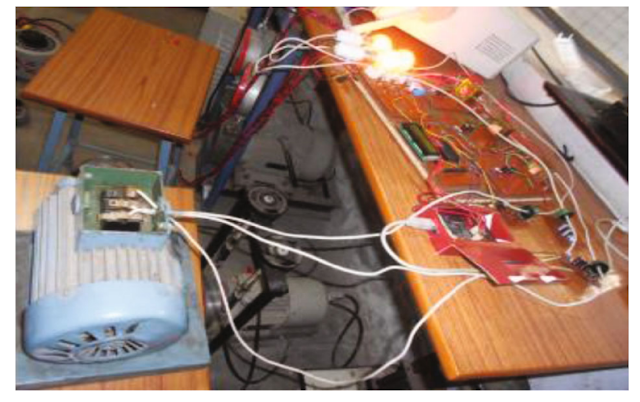
Three Phase Induction Motor Controller and Protection System

Three Phase Induction Motor Controller and Protection System

Three Phase Induction Motor Controller and Protection System

Components Used For Project "Three Phase Induction Motor Controller and Protection System":-

  • Atmega 328 Microcontroller
  • Encoder Sensor
  • Temperature Sensor
  • Vibration Sensor
  • Induction Motor
  • Switch Buttons
  • Status LED’s
  • Transformer
  • Regulatory Circuitry
  • PCB Board
  • Resistors
  • Capacitors
  • Transistors
  • Cables and Connectors
  • Grid Poles
  • Screws and Bolts

Description:

Induction Motors Have A Wide Range Of Applications, From Household Goods To Industrial Gear. This Calls For A Speed Control System That Is Effective And Secure To Operate. The Induction Motor May Also Be Operated In One Of Two Ways, Which Is Very Helpful In Many Applications.

But In Order To Handle Industrial Applications, Induction Motors, Like All Other Motors, Require Effective Control. Motors, Which Produce The Desired Motion In Any Machine, Are Also Among The Most Prone To Damage. As A Result, The System Also Includes A Temperature And Vibration Alarm.

The Advantages That This System Offers Are As Follows:

  • Using An App To Switch An Induction Motor
  • Motor Direction Control (Clockwise/anticlockwise) For Induction Motor
  • Motor Vibration Alert 
  • Motor Fire Protection

The Induction Motor Is Protected From Extreme Vibration And Temperature As Well As Controlled In Terms Of Speed And Direction By An Induction Motor Controller And Protection System. The Amount Of Power Applied To An Induction Motor Determines The Rpm At Which It Turns. It Uses A Direct Ac Line.

To Gauge The Motor's Rpm, We Employ An Encoder Sensor. In Order To Compute The Distance Travelled By The Motor, We Also Request The User's Input About The Wheel Size. Through The Use Of AC Driver Circuitry, We May Control The Power Of The Ac Line To Change The Induction Motor's Speed. To Provide PWM Power To An Opto-coupler, Which Drives The Triac Supplying Power To The Induction Motor, A Microcontroller From The Atmega Family Is Employed. A Bluetooth Connection To The System Is Used To Feed Instructions To The Microcontroller.

A Button To Change Direction, An App To Speed Up The Motor, And A Button To Slow It Down Are All Used With The Induction Motor. On The Lcd, The Entire Procedure May Be Seen As It Takes Place. This Project Demonstrates How Well It Can Control The Speed And Direction Of An Induction Motor In This Manner.


The Temperature Of The Induction Motor Is Now Measured Using A Temperature Sensor. The Sensor Is Used To Keep Track Of The Operating Temperatures Of Heavy-duty Induction Motors. The Sensor Continuously Measures The Motor's Temperature And Displays The Results On The Lcd. To Prevent Fires Or Coil Burning, The Device Shuts Off The Motor As Soon As The Temperature Exceeds A Certain Threshold.

In A Similar Manner, We Employ A Vibration Sensor To Keep Track Of Motor Vibrations While They Are In Use. On The Lcd Display, The Motor's Vibration Is Shown While It Operates. To Prevent Damage To The Machine Or Motor So That It Can Be Rectified Quickly And Prevent Any Mishaps, The System Shuts Off The Motor If The Vibration Rises Above A Specified Threshold. So, For Industrial Applications, The System Offers A Full Induction Motor Controlling And Protection System.


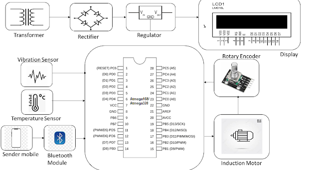
Block Diagrams

Three Phase Induction Motor Controller and Protection System

Important Notes:-


If You Looking For A Ready-Made Projects, Kindly Comments Below. 

We Will Provide You DIY Kits With Notebook To Submit In Your College Or School Or University.


Attention:-
Kindly Note That To View More Jobs Post , You Can Also Click On The Arrow "Right/Older Post" Or "Left/Pervious Post " Next To "HOME" Icons.

Electric Vehicle Wireless Charging Through Solar Energy

Solar Wireless Electric Vehicle Charging System

Electric Vehicle Wireless Charging Through Solar Energy

Components Required For Project "

Solar Wireless Electric Vehicle Charging System":-
  • Atmega Controller
  • Battery
  • Voltage Sensor
  • LCD Display
  • Transformer
  • Regulator Circuitry
  • Transmitter and Receiver Coils
  • Vehicle Body
  • Wheels
  • Switches
  • LED’s
  • PCB Board
  • Resistors
  • Capacitors
  • Transistors
  • Cables and Connectors
Description:-

The Number Of Electric Vehicles On The Road Today Is Steadily Increasing. In Addition To The Environmental Advantages, Electric Vehicles Have Demonstrated Usefulness In Lowering Travel Expenses By Substituting Electricity For Fuel, Which Is Significantly Less Expensive. However, There Are 2 Significant Drawbacks To Electric Vehicles:

  • It Takes A Long Time To Charge—between One And Three Hours.
  • Charging Facilities In Rural And Outlying Regions Are Not Powered.
Here, We Create An Innovative, One-of-a-kind EV Charging System That Addresses Both Of These Issues. The Advantages Of Using This EV Charging Setup Are As Follows:

  • Vehicles Can Be Wirelessly Charged Without Using Wires.
  • No Need To Stop Because The Vehicle Charges While It Is In Motion.
  • No External Power Source Is Required Because Solar Power Will Power The Charging System.
  • Road Coils Built In To Prevent Deterioration
Solar Panels, Batteries, Transformers, Regulator Circuits, Copper Coils, Ac To Dc Converters, Atmega Controllers, And Lcd Displays Are All Used In The System's Construction. The Method Shows How Electric Vehicles May Be Charged While Travelling Down The Road, Doing Away With The Need To Pull Over.

Through The Use Of A Charge Controller, The Battery Is Powered By The Solar Panel. DC Electricity Is Fed Into And Stored By The Battery. Now That The DC Power Is Ready For Transmission, AC Conversion Is Required. Here, We're Using A Transformer For This.

A Transformer Is Used To Convert The Power To AC, And Regulator Circuitry Is Used To Regulate It. The Copper Coils That Are Utilized For Wireless Energy Transmission Are Now Powered By This Energy. 

Additionally, A Copper Coil Is Installed Underneath The Electric Car. Energy Is Transmitted From The Transmitter Coil To The EV Coil When The Car Is Driven Across The Coils. 

Please Take Note That The Energy Is Still Induced Into This Coil As DC Current. To Enable Use In Charging The EV Battery, We Now Convert This Back To DC.

To Convert It Back To Dc Current, We Employ Circuitry For AC To DC Conversion. The Input Voltage Is Now Also Measured By An Atmega Microprocessor, And The Results Are Shown On An LCD Screen. 

As A Result, The Technology Shows How A Wireless Solar-powered Charging System For Electric Vehicles May Be Included Into The Road.

Block Diagram:


Important Notes:-


If You Looking For A Ready-Made Projects, Kindly Comments Below. 

We Will Provide You DIY Kits With Notebook To Submit In Your College Or School Or University.


Trending Posts This Month:-

System For Monitoring Plant Moisture | Electrical Engineering Projects Ideas

Smart Home Burglar Alarm Systems | Final Year Electrical Engineering Projects

Final Year Project Based On "Automatic Smoke Detector Alarm"

Solved Examples Problems On Star-Delta Transformation Or Conversion

Solved problem based on Norton’s Theorem

Solved Problem Based On Superposition Theorem

Example Solved Problems Based On Thevenin Theorem Circuit

Tricky Solutions For Equivalent Series-parallel Resistance Problems With Examples

Solved Problem Based On Maximum Power Transfer Theorem

Mesh-analysis - Loop-analysis -Maxwell's Current Analysis | Electrical

Delta To Star Transformation Or Delta To Star Conversion and Its Formulas

Superposition Theorem And Method Of Solving Superposition Theorem

Reading Problems Based On Superposition Theorem Example & Solved Formula's


Friday, 13 January 2023

Final Year Project Based On "Automatic Smoke Detector Alarm"

Final Year Project Based On "Automatic Smoke Detector Alarm" | How To Make "Smoke Detector Alarm Circuit"


A Quick Overview Of Smoke Sensors:

- Smoke Detectors Come In Two Different Varieties. Ionization Smoke Detectors And Optical Or Photoelectric Smoke Detectors.

- A Light Source, Such As An Led, And A Light Detector, Such As A Photocell, Make Up Optical Smoke Detectors.

- As Long As Light Shines On The Photocell, It Will Conduct. The Photocell Doesn't Conduct When There Is Smoke Because The Source's Light Is Obscured.

- Two Electrodes And An Ionization Chamber With Ions Are The Components Of Ionization Smoke Detectors. The Ions Travel Freely And The Electrodes Conduct Normally When There Is No Smoke.

- Smoke Causes The Chamber To Fill With Smoke, Which Stops The Ions From Moving. The Electrodes Are No Longer Conducting. 

- The Conductivity Conditions May Vary Depending On The Sensor Type And Manufacturer, But The Concept Is The Same.

- A Smoke Detector's Output Can Be Used To Set Up An Alarm System.

- The Mq-2 Gas/smoke Sensor Is The Sensor Utilised In This Research. It Is Sensitive To Flammable Gases Used In Industry, Including Butane, Alcohol, Hydrogen, Smoke, Methane, And Hydrogen.

- Aluminum Oxide (Al2o3) Is Used For Both Of Its Electrodes, While Tin Dioxide (Sno2) Is Used For The Heating Element, Which Also Serves As The Primary Sensing Layer.


Equipment's Required For ""Automatic Smoke Detector Alarm" Circuits:-
  • Cables and Connectors
  • Diodes
  • PCB and Breadboards
  • LED
  • Push Buttons
  • Switch
  • IC
  • IC Sockets
  • Battery
  • I R Transmitter Receiver
  • 555 Timer IC
  • Buzzer
  • Resistors
  • Capacitors
  • Transistors
Descriptions:-

- In The Event Of A Fire, The Interior Spaces Of The Building Are Filled With Smoke. This Smoke Cloud Gradually Gets So Thick That It Significantly Reduces Visibility. This Information Can Be Used To Build A Straightforward Smoke Detector Alarm That Can Warn Nearby Households Of A Fire Outbreak.

- Because It Doesn't Use Expensive Smoke Detecting Sensors, The Automatic Smoke Detector Alarm Is Quite Small. 

- It Contains Two Infrared Sensors That Continuously Check The Lighting Conditions In The Area Where They Are Mounted.

- If A Fire Starts, Smoke Is Produced And Travels Throughout The Building. The Infrared Sensors' Ability To Detect Smoke Get Obscured After It Enters The Smoke Detector Module. 

- The Detector Module Activates A Fire Alarm As A Result. Residents Nearby Can Become Aware Of The Fire And Leave The Area After Hearing This Alarm. 

- The Alarm Continues To Ring While There Is Smoke Present And Turns Off Once The Smoke Has Cleared.

- The Opaqueness Attribute Of Smoke Serves As The Organizing Basis For This Endeavour. The Infrared Sensors Are Constantly Visible To One Another In The Absence Of Smoke. 

- The Sensor Output Changes As Soon As Smoke Enters The Field Of View And Blocks The Sensor Signal. 

- The System Detects This Alteration And Sounds An Alarm To Warn The Nearby Residents Of The Fire Outbreak.

Block Diagram:

Automatic Smoke Detector Alarm

Important Notes:-


If You Looking For A Ready-Made Projects, Kindly Comments Below. 

We Will Provide You DIY Kits With Notebook To Submit In Your College Or School Or University.

Trending Posts This Month:-

Solved Examples Problems On Star-Delta Transformation Or Conversion

Solved problem based on Norton’s Theorem

Solved Problem Based On Superposition Theorem

Example Solved Problems Based On Thevenin Theorem Circuit

Tricky Solutions For Equivalent Series-parallel Resistance Problems With Examples

Solved Problem Based On Maximum Power Transfer Theorem

Mesh-analysis - Loop-analysis -Maxwell's Current Analysis | Electrical

Delta To Star Transformation Or Delta To Star Conversion and Its Formulas

Superposition Theorem And Method Of Solving Superposition Theorem

Reading Problems Based On Superposition Theorem Example & Solved Formula's

Thursday, 12 January 2023

Smart Home Burglar Alarm Systems | Final Year Electrical Engineering Projects

Smart Home Burglar Alarm Systems Final Year Electrical Engineering Projects | Smart Burglar Alarm Mini Project Kit | Best Smart Alarm Systems In 2023


Hardware Materials Requirements:-
  • Cables and Connectors
  • Diodes
  • PCB and Breadboards
  • LED
  • Transformer/Adapter
  • Buzzer
  • 555 Timer IC
  • Resistors
  • Capacitors
  • Transistors
  • Push Buttons
  • Switch
  • IC Sockets
  • Battery
Descriptions:-

- Nobody Wants To Experience A Break-in At Their Home Or Business. However, It Is Challenging For Anyone To Be On Guard Constantly To Defend Their Property. 

- This Easy-to-use Tool, The Smart Burglar Alarm, Assists In This Case By Sounding An Alarm Whenever An Unauthorised Entry Is Made Into A Secured Area.

- A Copper Wire Loop That Is Installed At The Entrance To The Secured Area Serves As The Foundation For The Smart Burglar Alarm. 

- The System Activates A Connected Alarm When A Burglar Enters The Area And Breaks The Loop. 

- The Inhabitant Of The Business Or Residence Can Become Aware Of The Intrusion And A Potential Burglary By Hearing The Alarm.

- Until The System Is Switched Off Or The Wire Loop Is Reconnected, The Alarm Will Sound.

- The Conductivity Of A Long Copper Wire, Which Switches A Transistor In Its Absence, Forms The Basis Of The Project's Working Principle. 

- The System Flips The Transistor So That The Alert Is Turned Off When The Copper Wire Loop Is Present. 

- On The Other Hand, When The Copper Wire Is Severed, The Transistor Switch Complements And The Alarm Is Activated. 

- As A Result, The User Is Informed Of The Intrusion.

Reference Block Diagram:-

Important Notes:-

If You Looking For A Ready-Made Projects, Kindly Comments Below. 

We Will Provide You DIY Kits With Notebook To Submit In Your College Or School Or University.

System For Monitoring Plant Moisture | Electrical Engineering Projects Ideas

System For Monitoring Plant Moisture | Electrical Engineering Projects Ideas


Hardware Requirements:
  • LED
  • Transformer/Adapter
  • Push Buttons
  • Switch
  • IC
  • IC Sockets
  • Water Sensor
  • Buzzer
  • Resistors
  • Capacitors
  • Transistors
  • Cables and Connectors
  • Diodes
  • PCB and Breadboards

Description For Project "System For Monitoring Plant Moisture":-

- It Has Always Been A Problem For Tree Planters To Plant Trees In Areas Where The Seed Or Plant Will Not Receive Enough Water From Natural Sources, Such As Rain Or Ground Water, During Its Early Stages. 

- An Autonomous Moisture Sensor For Plants System Can Be Useful In This Situation.

- The Technology Continuously Checks The Soil's Moisture Content. 

- An Audible Visual Alarm Will Be Raised If It Is Discovered During Monitoring That The Soil's Moisture Level Is Lower Than Is Ideal. 

- The Plant's Caretaker Subsequently Receives This Alert. The Alert Sounds And The Cycle Of Monitoring Resumes When The Plant Is Watered By The Caretaker.

- In This System, The Monitoring Process Is Timed Using A Timer Ic. The Moisture Content Of The Soil Is Determined Using A Moisture Level Sensor. 

- The Plant Caretaker Will Receive An Auditory Alarm From A Buzzer And A Visual Signal From An Led. 

- Thus, In This Project, We Can Manage A Plant's Soil's Moisture Level, Keeping The Plant Healthy, With The Aid Of A Straightforward Combinational Circuit And A Sensor.


Block Diagram For Reference:

System For Monitoring Plant Moisture | Electrical Engineering Projects Ideas