Showing posts with label Theory. Show all posts

Thursday, 6 October 2022

Delta Wye Transformation Formula, Delta to Star Conversion, Delta Wye Example

Delta Wye Transformation Formula, Delta to Star Conversion, Delta Wye Example

In this chapter, we will learn about “How to convert a delta to star/wye connection in a circuit/network”.

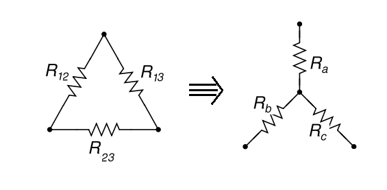
Below is the example of a Delta network, for which we will convert this circuit from Delta to WYE circuit.

Delta Wye Transformation Formula, Delta to Star Conversion, Delta Wye Example
Follow the step as below explained:-

We have R12, R13 and R23 resistances connecting to each other such that they form a delta connections.

 Special Note’s:-

Firstly understand that Why It is important to know the conversation/transformation of a “delta to wye or wye to delta”.

For example, If a circuit required to calculate equivalent resistance then sometimes it is impossible to simply the circuit by any other method specially if it form a delta or wye connection. By this way, we can easily used formula to determine the equivalent resistance for the given circuit.

Let’s Move Forward With Topic:-


Delta Wye Transformation Formula, Delta to Star Conversion, Delta Wye Example

Draw a imaginary dot line in such a manner that it form Star by connecting point 1, point 2 & point 3 to mid of the delta circuit that they form star connection as explained below:-

This is Called “Star/Wye Connection” for the new network.

For Star/Wye circuits the new resistances is R , RB and RC  having new resistance value’s.

For R , RB and RC , we have direct formula’s which we will use, No need of derivation.

Kindly used and note down in your notebook direct formulas for “Delta To Wye/Star” as given below:-Delta Wye Transformation Formula, Delta to Star Conversion, Delta Wye Example
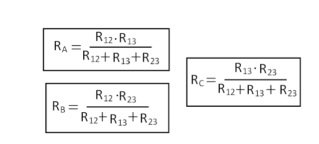
Examples based on this formula are in our next post. Kindly check next topic for more practical details.


How to remember?

Resistance of each arm of the star is given by the product of the resistances of the two delta sides that meet at its end divided by the sum of the three delta resistances”.


Kindly Checkout Other Topics for More Deep Practical Knowledge.

Thanks For Reading & Learning.


 Trending Posts This Month:-

Solved Examples Problems On Star-Delta Transformation Or Conversion

Solved problem based on Norton’s Theorem

Solved Problem Based On Superposition Theorem

Example Solved Problems Based On Thevenin Theorem Circuit

Tricky Solutions For Equivalent Series-parallel Resistance Problems With Examples

Solved Problem Based On Maximum Power Transfer Theorem

Mesh-analysis - Loop-analysis -Maxwell's Current Analysis | Electrical

Delta To Star Transformation Or Delta To Star Conversion and Its Formulas

Superposition Theorem And Method Of Solving Superposition Theorem

Reading Problems Based On Superposition Theorem Example & Solved Formula's

Saturday, 4 June 2022

Wheatstone Bridge Concept | Wheatstone Bridge Circuit Diagrams

Wheatstone Bridge Concept | Thevenin Equivalent Circuit of Wheatstone Bridge Theory | Wheatstone Bridge Circuit Diagrams

Wheatstone Bridge Definition:-

This is the simplest bridge to measure resistance. Figure 14.22 shows the schematic of a Wheatstone bridge. The bridge has four resistive arms together with a source of emf and detector, usually a galvanometer or other sensitive current meter.

If the sensitivity of the galvanometer is not sufficient to indicate the balance position to the required degree of precision, then the measured value of R, can have some error.


Thevenin Equivalent Circuit of Wheatstone Bridge:-

To find whether or not the galvanometer has the required sensitivity to detect an unbalance condition, it is necessary to calculate the galvanometer current. The Thevenin equivalent circuit is determined by looking into the galvanometer terminals 'c' and 'd' no as shown in Fig. 14.23.


NOTE:- The Kelvin bridge is more accurate than the Wheatstone bridge and is used for measuring very low resistances.


Trending Posts This Month:-

Solved Examples Problems On Star-Delta Transformation Or Conversion

Solved problem based on Norton’s Theorem

Solved Problem Based On Superposition Theorem

Example Solved Problems Based On Thevenin Theorem Circuit

Tricky Solutions For Equivalent Series-parallel Resistance Problems With Examples

Solved Problem Based On Maximum Power Transfer Theorem

Mesh-analysis - Loop-analysis -Maxwell's Current Analysis | Electrical

Delta To Star Transformation Or Delta To Star Conversion and Its Formulas

Superposition Theorem And Method Of Solving Superposition Theorem

Reading Problems Based On Superposition Theorem Example & Solved Formula's
Monday, 4 April 2022

Definition Of Energy Transformations - Energy Transfer Law Examples

Definition Of Energy Transformations | The Law of Energy Conversion | Energy Transfer Law Examples 

ENERGY CONVERSION

Electric energy is obtained by conversion from other forms of energy stored in naturally occurring materials or from energy being continuously received from the sun in its primary form or in its secondary manifestations, for example, rain, snow at high altitude, wind, plants etc.

Energy is stored in natural materials (coal, oil and gas and in the atom) in a chemical form. Coal, oil and gas (methane) were formed by natural processes over enormous periods of time aeons ago. These are available near the earth surface or underground, mostly at great depths, particularly, oil and gas. These are limited resources provided by nature and are non replenish able. Their extraction leaves gorges, which, when near earth surface, render vast tracts of land unfit for use. It is not clearly known what effect is caused by voids deep under the earth caused by oil extraction.

Energy from the atom (nuclear energy) can be obtained from certain materials with a high atomic number like uranium/thorium. Their resources are also limited, though they contain a great amount of energy.

Energy directly received from the sun (during day time) can be used directly (to be elaborated later in Next Post), but the surface density of solar energy is quite low and is variable during day, cloudy weather and different seasons. It is the solar energy which is responsible for rain/snow and winds. Rain collected at high altitude has potential energy and winds possess kinetic energy. 

Further, trees, plants and vegetation absorb solar energy, which is stored there in a chemical form. Pull of the moon on earth imparts energy to sea water in the form of tidal waves. High winds cause energy to be imparted to sea waves. Energy in the forms enumerated here are replenish able (renewable) and further they are nonpolluting, when used for conversion to the electric energy form.

The aim of this section is to describe various means and processes for converting the above listed energy forms to electric energy. With certain exceptions this conversion requires the first step of conversion to rotational mechanical energy, which then is used to run a generator for conversion to electric form. As only very small quantities of electric energy can be stored and that also mainly by chemical means, it has to be continuously generated and transported to use points.

A panoramic view of energy conversion to electric form is presented As below:-

Definition Of Energy Transformations | The Law of Energy Conversion | Energy Transfer Law Examples

which at a glance brings into focus all aspects of electric energy including conservation. A similar pictorial view of all the related issues in electric energy-generation, efficiency, nature, environmental impact and use classification is given above will be discussed in fair detail in various sections of this chapter.

Energy is converted to a mechanical rotational form by means of the following turbines.

  • Steam turbine
  • Gas turbine
  • Hydraulic turbine

Steam is raised in a boiler by heat released by combustion of coal/oil or by atomic fission in a suitable vessel called the reactor. 

Combustion and steam raising is combined into a single boiler unit for coal-oil-based operation. However, in fission process, steam is raised by heat exchange processes from the reactor to boiler (or directly in the reactor). 

A gas turbine directly extracts energy from the products of combustion. In a hydraulic turbine, water's potential energy is directly converted to a rotational form.


Saturday, 12 March 2022

Transformers - Simple Transformer - Core Type Transformer - Shell Type Transformer

What Is Transformers? Definition Of A Simple Transformer | Core Type Transformer | Shell Type Transformer

INTRODUCTION:-

Economical and technologically feasible voltage levels at which large chunks of electric power can be generated are typically 11-37 kV, while the most convenient utilization voltages are 230/400 V for industrial, commercial and domestic purposes.

Large industrial motors may be run at 3.3, 6.6 or 11 kV. It is impossible to transmit directly, even over modest distances, the electric power as it is generated (11-37 kV). Unacceptably large power losses and voltage drops would result. As a rule of thumb economical transmission voltage is 0.625 kV/km line-to-line, e.g. 400 kV for a line of about 640 km. It is therefore essential to step-up voltages at the sending (generating) end and to step-down at the receiving end. Usually more than one step of Step-down may be necessary. Step-up and step-down of voltage levels is accomplished by means of static electromagnetic devices called Transformers.


It was seen in alternating flux is set up in a core by a coil excited with ac voltage, which in turn induces coil emf (The magnitude of flux is determined by the fact that the coil emf must equal the excitation voltage (KVL) ) of excitation frequency proportional to the number of coil turns. 

If another coil is wound on the same core, the mutual flux (alternating) would induce emf in it also of the same frequency and of magnitude proportional to its coil turns. The ratio of the voltage of the two coils can be easily adjusted by means of their turn-ratio. 

Such a device, which indeed is a mutually coupled circuit, is called a Transformer and is exhibited diagrammatically in Fig. Below:-

SIMPLE TRANSFORMER

PIC:- 1 -  "A SIMPLE TRANSFORMER"

The coil excited from the ac source is called the primary and receives electric power from the source. The other coil is called the secondary and the voltage induced in it could be used to feed a load. The subscript '1' will be associated with the primary and '2' with the secondary. Primary and secondary roles in a transformer are easily reversed by the prevailing electrical conditions at the two ports. To avoid confusion in practice the two transformer coils are known as HV (high-voltage) and LV (low-voltage) windings.

Also shown in  are the mutual and leakage flux paths. Since a significant part of the leakage flux paths is through air, leakage fluxes Φ11 and Φ12 are less than the mutual flux Φ .

The dots indicate on the two coils (windings) are the polarity marks. As the mutual flux alternates, these coil ends simultaneously acquire the same polarity. Also current into the dot in one coil and out of the dot in the other coil would tend to produce core flux in the opposite direction.

The transformer shown in PIC:- 1 is an iron-core transformer. Transformers operated at 25-400 Hz are invariably of iron-core construction. 

In special cases (particularly at high frequencies), the core may be made of nonmagnetic material in which case it is called an air-core transformer. Application range for air-core transformers are radio devices and certain types of measuring and testing instruments.

Since the transformer core carries alternating flux, it is made of laminated steel (0.35 mm thickness for 50 Hz transformers). The transformer core is constructed of rectangular sheet steel strips. Two types of core constructions are adapted for single-phase transformers-core and shell type as below:-

(a) Core Type Transformer  (b) Shell Type Transformer

              PIC:- 2 - (a) Core Type Transformer  (b) Shell Type Transformer

The core type construction has a longer mean length of flux path and a shorter mean length of coil turn.

Flux linking only one winding of the transformer (leakage flux) is detrimental to transformer performance in terms of voltage drop. To reduce leakage flux half-LV and half-HV are wound on each limb of the core type transformer as shown in PIC:- 2 - (a)

For economical insulation, the LV coils are placed inside (next to core) and HV coils are placed on the outside. In a shell type transformer reduced leakage flux is achieved by sandwiching HV and LV coil packets.

To prevent ingress of moisture and deterioration of winding insulation, the built-in core and windings are placed in a steel tank filled with transformer oil. 

Oval or circular tubes are provided on the outside surfaces of the transformer tank, aiding in natural circulations of oil, which removes the heat of core and winding (I2R) losses and transports it to the tank surfaces for cooling purpose. Oil circulations also removes the heat generated by iron losses in the core. 

To prevent the coil from absorbing moisture from air and from being oxidized, the tank must be sealed and connected to the atmosphere through a narrow passage for breathing purposes. Inside this passage is placed silica gel for drying the air that the transformer breathes in.

Tuesday, 1 March 2022

Work, Energy And Power - Principal Of Conservation Of Energy

Definition Of Work, Energy And Power | Principal Of Conservation Of Energy 

WORK:-

Work is done whenever an object moves in a field of force, F (unit of force is Newton, N). If the object moves in the direction of force, work is done by the force.

However, if the object moves in a  direction opposite to the force, work is done by an external agency that moves the object.

ENERGY:-

It is the capacity for doing work. when a weight is lifted against gravity, work done by an external agency in lifting it gets stored in the weight as potential energy(by virtue of its position in the gravitational force field). 

If the weight were now allowed to fall the potential energy will get converted to kinetic energy (associated with velocity). 

Further, if the weight were to fall on a wedge, it will drive it into a piece of wood(say) thereby doing work. The process of doing work in some sense is a process of energy transfer. 

In the example cited above energy is transferred from the external agency to the weight and get stored as potential energy. When the weight falls, it still remains stored in the weight but gets converted to kinetic energy. Upon hitting the wedge, it gets transformed to heat in driving the wedge against wood friction.

Energy, W is measured in unit of Joules, J Or Newton-Metres, N-m, as it equals force N X Distance Moved (m).

PRINCIPLE OF CONSERVATION OF ENERGY:-

In Non-relativistic processes energy never gets destroyed; it gets converted from one form to another as illustrated in the above example.

Power

It is the rate of doing work(i.e., rate of transferring energy). Instantaneous power is


Average power is given by


The integral forms of Picture (A) are


Trending Posts This Month:-

Solved Examples Problems On Star-Delta Transformation Or Conversion

Solved problem based on Norton’s Theorem

Solved Problem Based On Superposition Theorem

Example Solved Problems Based On Thevenin Theorem Circuit

Tricky Solutions For Equivalent Series-parallel Resistance Problems With Examples

Solved Problem Based On Maximum Power Transfer Theorem

Mesh-analysis - Loop-analysis -Maxwell's Current Analysis | Electrical

Delta To Star Transformation Or Delta To Star Conversion and Its Formulas

Superposition Theorem And Method Of Solving Superposition Theorem

Reading Problems Based On Superposition Theorem Example & Solved Formula's


Sunday, 23 March 2014

Delta To Star Transformation Or Delta To Star Conversion and Its Formulas

Delta To Star Transformation Or Delta To Star Conversion and Its Formulas

Fig:-
delta-wye transformer neutral grounding

Suppose, R12  , R13 and R23 is three resistances connecting to each other such that they forms a delta connections or star networks.

 Now, we have to convert this circuit in star for solving or simplifying given star connected circuits. Because if you are not convert may not get equivalent resistances of that given circuit.
Fig:-
star delta connection of transformer pdf

So, we make a star connection by connecting pt.1, pt.2 and pt.3 to pt. O such that they form as star connection as shown in fig. It will form a new network as ‘Star connection’ as I shown through dotted diagram and hence forms a new ‘Star circuit’.

For new circuits containing new resistances is RA  , RB and RC  having new value’s. For these new resistances we have direct formula’s I am going to give you because no need of derivation, kindly used direct formulas as given below:-


transformer connection diagram

How to remember?


Resistance of each arm of the star is given by the product of the resistances of the two delta sides that meet at its end divided by the sum of the three delta resistances”.


Friday, 14 February 2014

Star To Delta Transformation Or Star To Delta Conversion And Formulas

STAR TO DELTA TRANSFORMATION OR STAR TO DELTA CONVERSION AND FORMULAS

Fig:-
transformer connection diagram formula

Suppose, RA  , RB and RC is three resistances connecting to each other such that they forms a star connections or star networks.

 Now, we have to convert this circuit in delta for solving or simplifying given star connected circuits. Because if you are not convert may not get equivalent resistances of that given circuit.

Fig:-
3 phase transformer calculation formulas

So, we make a delta connection. Connecting pt.1 to pt.2 and pt.3 and also connecting pt.2 to pt.3. It will form a new network as ‘delta connection’ as I shown through dotted diagram and hence forms a new ‘Delta circuit’.

For new circuits containing new resistances is R12  , R13 and R23 having new value’s. For these new resistances we have direct formula’s I am going to give you because no need of derivation, kindly used direct formulas as given below:-

Fig:-
3 phase transformer calculator

How to remember?

The equivalent delta resistance between any two terminals is given by the sum of star resistances between those terminals plus the product of these two star resistances divided by the third star resistance”.

Monday, 5 November 2012

Maximum Power Transfer Theorem Definition And its solution Formula's

Maximum Power Transfer Theorem Definition And its solution Formula's

Maximum power transfer theorem can be explained by using Thevenin’s equivalent circuit. 

So, the problem of this theorem is also solved by same steps as we done in “Thevenin’s Theorem and method of solving”.

Maximum power transfer theorem
Here,
Vth replaced by Vo.c.
Rth replaced by Ro.c. &
RL is same at is.

In maximum power transfer theorem, we are doing this process for open circuit. i.e, from where load-resistance RL is removed.

Now,
maximum power transfer theorem solved problems
Maximum power delivered to the load is found from the given condition is,
steps to solve maximum power transfer theorem

RL= Ro.c ,This condition of states that the power delivered or transferred to load resistance is maximum when load-resistance equals the Thevenin’s equivalent resistance i.e, Ro.c is known as the “Maximum power transfer theorem”.

Then,

Monday, 15 October 2012

Norton’s Theorem Statement And Norton’s Theorem solved Method

Norton’s Theorem Statement And Norton’s Theorem solved Method


Consider a circuit,

The solution of the given problem is not done by the actual given circuit, we have to find-out the value of any unknown (i.e, V,I or P) through any resistance as per question is said we design a new circuit and the circuit is known as “Norton’s equivalent circuit”.

Norton’s equivalent circuit has containing one current source in parallel with two resistances ‘RL’ & ‘RN’. As shown in fig. below:-

Here,
IN/IS.C = Norton’s equivalent current (“It is that Current from required unknown through any resistance is removed and short-circuited.”)

RN =Norton’s equivalent resistance (“It is that equivalent resistance from required unknown through any resistance is removed”) &

RL =Called “Load-Resistance” (The resistance in which unknown is required).

Method Of Solving “Norton’s Theorem”:-

For finding RL: - Suppose that from above given circuit, asked to find-out the value of current through ‘R4’ resistance. Then the resistance along which any unknown is asked to find-out that resistance becomes “Load-resistance”.
Here, RL=R4

For finding RN: - For finding RN, Just find-out equivalent b/w removed load-resistance. Like as:-
Step 1st:- Firstly removed the load-resistance from the given circuit

Step 2nd:- Deactivating all the energy sources of the fig. Step 1st:-

Step 3rd:- Now, RN is actually the equivalent resistance b/w that two ends from load-resistance are removed of fig. Step 2nd:-
For finding IN/IS.C: - For finding IN/IS.C in given circuit diagram, we have to follow the given steps:-
Step 1st:- Removed load-resistance from the given problem circuit.

Step 2nd:- Short-circuit the open part from where the load-resistance is removed.

The current flow through short-circuited path is the required current IN/IS.C  which we can find-out any of the method we have studied earlier in this website.(Easy to use Mesh-analysis) 
                            
Now, the Norton’s equivalent circuit is,

By using current division rule, we can easily find-out the value of IR4 Ω in the given problem.