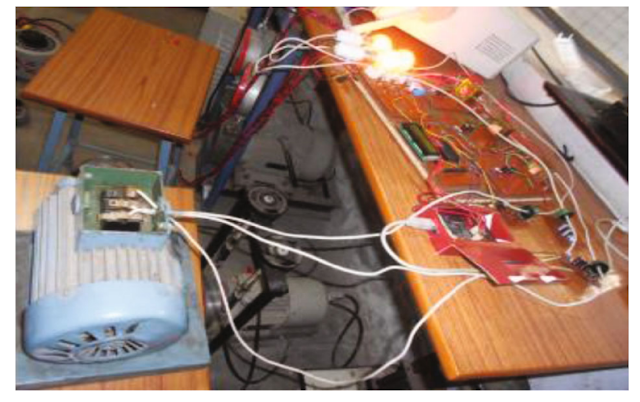
Three Phase Induction Motor Controller and Protection System
Components Used For Project "Three Phase Induction Motor Controller and Protection System":-
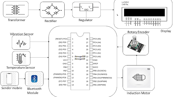
- Atmega 328 Microcontroller
- Encoder Sensor
- Temperature Sensor
- Vibration Sensor
- Induction Motor
- Switch Buttons
- Status LED’s
- Transformer
- Regulatory Circuitry
- PCB Board
- Resistors
- Capacitors
- Transistors
- Cables and Connectors
- Grid Poles
- Screws and Bolts
The Advantages That This System Offers Are As Follows:
- Using An App To Switch An Induction Motor
- Motor Direction Control (Clockwise/anticlockwise) For Induction Motor
- Motor Vibration Alert
- Motor Fire Protection
The Induction Motor Is Protected From Extreme Vibration And Temperature As Well As Controlled In Terms Of Speed And Direction By An Induction Motor Controller And Protection System. The Amount Of Power Applied To An Induction Motor Determines The Rpm At Which It Turns. It Uses A Direct Ac Line.
To Gauge The Motor's Rpm, We Employ An Encoder Sensor. In Order To Compute The Distance Travelled By The Motor, We Also Request The User's Input About The Wheel Size. Through The Use Of AC Driver Circuitry, We May Control The Power Of The Ac Line To Change The Induction Motor's Speed. To Provide PWM Power To An Opto-coupler, Which Drives The Triac Supplying Power To The Induction Motor, A Microcontroller From The Atmega Family Is Employed. A Bluetooth Connection To The System Is Used To Feed Instructions To The Microcontroller.
A Button To Change Direction, An App To Speed Up The Motor, And A Button To Slow It Down Are All Used With The Induction Motor. On The Lcd, The Entire Procedure May Be Seen As It Takes Place. This Project Demonstrates How Well It Can Control The Speed And Direction Of An Induction Motor In This Manner.
The Temperature Of The Induction Motor Is Now Measured Using A Temperature Sensor. The Sensor Is Used To Keep Track Of The Operating Temperatures Of Heavy-duty Induction Motors. The Sensor Continuously Measures The Motor's Temperature And Displays The Results On The Lcd. To Prevent Fires Or Coil Burning, The Device Shuts Off The Motor As Soon As The Temperature Exceeds A Certain Threshold.
In A Similar Manner, We Employ A Vibration Sensor To Keep Track Of Motor Vibrations While They Are In Use. On The Lcd Display, The Motor's Vibration Is Shown While It Operates. To Prevent Damage To The Machine Or Motor So That It Can Be Rectified Quickly And Prevent Any Mishaps, The System Shuts Off The Motor If The Vibration Rises Above A Specified Threshold. So, For Industrial Applications, The System Offers A Full Induction Motor Controlling And Protection System.
Important Notes:-
Popular Posts This Month
Solved Examples Problems On Star-Delta Transformation Or Conversion
Solved Problem Based On Superposition Theorem
Solved problem based on Norton’s Theorem
Example Solved Problem Based on Mesh Analysis Or Mesh Method
Example Solved Problems Based On Thevenin Theorem Circuit
Reading Problems Based On Superposition Theorem Example & Solved Formula's
Electric Vehicle Wireless Charging Through Solar Energy
Tricky Solutions For Equivalent Series-parallel Resistance Problems With Examples
Solve Example of Wye Delta Transformation, WYE to Delta Conversion, Star Delta Connector
Solved Problem Based On Nodal Analysis Or Nodal Method Of Circuit Analysis


No comments:
Post a Comment
Thanks for your feedback.